info@qilowatt.lv I +371 29351873
Creating a user account
To create a user account, open the website https://app.qilowatt.it and follow the instructions there.
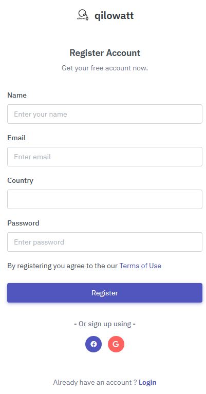
When opening the app, log in with your Google account or register with an email address by clicking the “Signup now” button.
Fill in the required fields and click “Register.” A confirmation email will then be sent to your email address, after which you can log in to the app immediately.
When opening the app, log in with your Google account or register with an email address by clicking the “Signup now” button.
Fill in the required fields and click “Register.” A confirmation email will then be sent to your email address, after which you can log in to the app immediately.
Connecting the device to a WiFi network
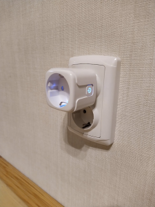
Connect the device to a power source
Make sure the device’s blue light starts blinking.
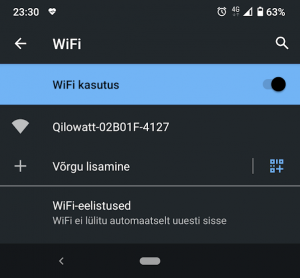
Connect your phone to the device’s WiFi network.
When the device is connected to the power grid for the first time, it will start broadcasting a WiFi network with a name (SSID) beginning with “Qilowatt.” Connect your smartphone to this network.
Watch the video: https://youtu.be/V01gKeDQnhA
Watch the video: https://youtu.be/V01gKeDQnhA

Allow the device to connect to your home internet.
When you click on the WiFi connection, the following dialog will open automatically, or you may need to open the address http://192.168.4.1 in a web browser:
In the first field, enter the email address used in step one of the guide.
In the second field, enter the WiFi network name that the smart switch will use to connect to the internet.
The third field has a checkbox that, when selected, will display the entered password in letters instead of asterisks. We recommend using this option to ensure the password is entered correctly.
Then, by clicking the “Save” button, the device’s connection parameters will be stored.
NB!
The home network name (SSID) may only contain letters of the Latin alphabet and numbers. Spaces and special characters are not recognized. The maximum allowed length is 32 characters.
2.4GHz WiFi networks are supported.
Thermostat installation and setup
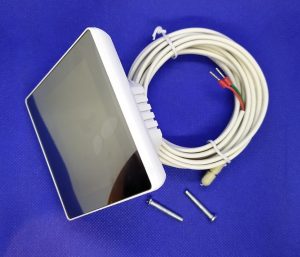
1.1. The set includes a control unit and a moisture-resistant temperature sensor. It can be installed in a standard junction box with a depth of at least 25 mm. The dimensions shown in the following diagram should also be taken into account.
For thermostat installation, the mounting frame and display need to be separated. To do this, hold the display and press the rear frame section downward by about 5 mm. Then disconnect the connector that links the two parts.
Watch video on url : https://www.youtube.com/watch?v=nXft_-U-9K4
Watch video on url : https://www.youtube.com/watch?v=nXft_-U-9K4
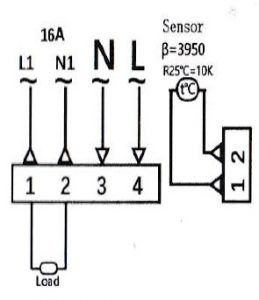
1.3. The wires are connected according to the diagram:
1 – heating element phase *
2 – heating element neutral *
3 – mains neutral
4 – mains phase
On sides 1 and 2, the connections are for the thermostat; the order of the wires does not matter.
* In most cases, the polarity of heating elements is not important.
The maximum allowed load is 16 amps, which equals about 3500 watts at 230 volts.
Please note:
1) Stranded wire ends must be crimped with ferrules or soldered. Solid wires do not require ferrules.
2) If the power exceeds 2000 W, the wire cross-section must be at least 2.5 mm².
3) The heating device must be grounded.
After connecting the wires, install the thermostat into the junction box, attach the display connection cable, and press the display back into its original position.
2.1. Screen indicators:
1 – Time
2 – Day of the week
3 – Current temperature
4 – Period
5 – Touch buttons for settings
6 – Temperature setpoint
7 – Child lock
8 – Power-on indicator (heating element energized)
9 – Operating mode (manual or automatic)
2.2. To set the time, tap the clock icon once (button 2 in the bottom row). The hour digits will start blinking—use the up or down arrows on the right to select the correct hour.
Tapping the clock icon again activates the minute setting. Use the same up and down arrows to adjust the minutes.
On the third tap of the clock icon, the day of the week selection is activated.
On the fourth tap, the settings are saved.
2.3 There are two operating modes: manual (hand icon indicator) or automatic (time and temperature).
2.3.1 To activate manual mode, press the “M” button until the hand icon appears in the operating mode. Then use the arrow buttons to select the desired temperature.
2.3.2. The indicator for automatic mode is the clock icon. When it is illuminated, the following preset is applied.
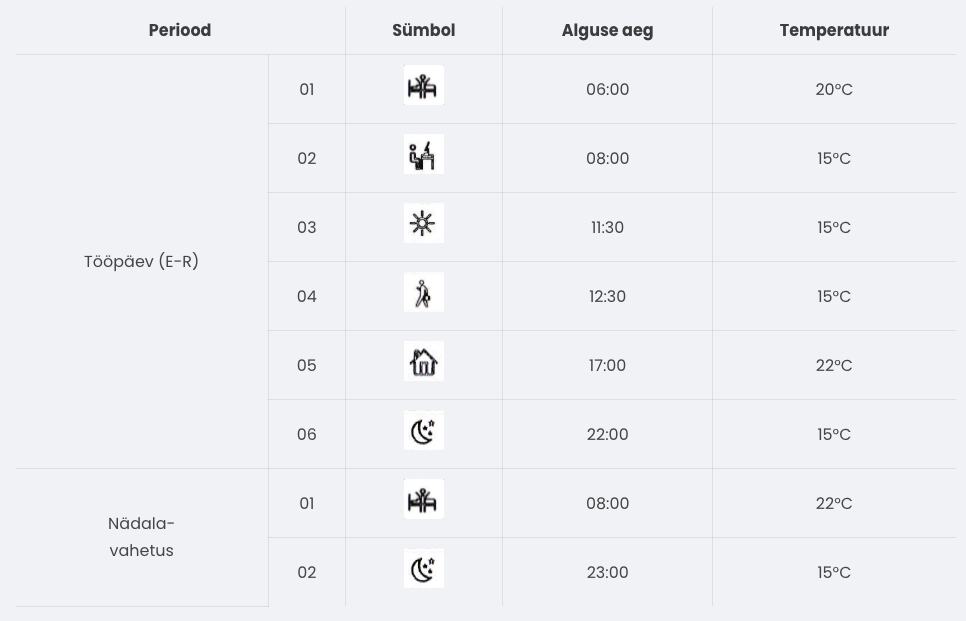
To change the preset, turn the device off and then press and hold the “M” and clock buttons simultaneously for five seconds. The setup menu will then appear on the screen, showing the preset fields. The active field will blink and can be adjusted using the arrow buttons. Pressing the “M” button moves to the next field. When the setup is complete, confirm by pressing “M.”
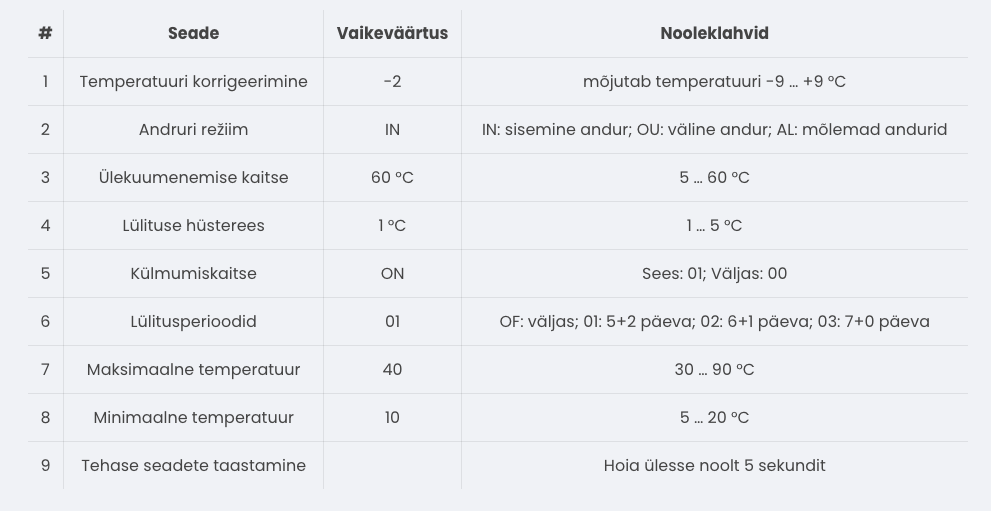
2.4 The device has frost protection. It switches on when the temperature drops below 5 °C and switches off when the temperature rises above 7 °C. By default, overheating protection is activated at 60 °C.
2.5 Advanced settings allow you to change the device’s operating parameters and perform the initial setup. To access this menu, turn off the device and press the “M” and down arrow buttons. Use the “M” button to switch between options. To exit the mode, press the power-off button.
Connecting the thermostat to the qilowatt.it app
Integration with https://app.qilowatt.it follows the device connection guide. Through the Qilowatt app, the thermostat can be switched on and off automatically over the internet. When switched on, the thermostat applies the temperature set for the corresponding period.
Resetting WiFi settings
Heat pump installation
Supported models
Make sure your model is supported by Qilowatt. If you cannot find your device in the list, please contact us and we will find a solution.
NB! All electrical connections must be made by a certified electrician. Installation can also be ordered from us—please arrange the time and place by emailing info@qilowatt.it.
NB! All electrical connections must be made by a certified electrician. Installation can also be ordered from us—please arrange the time and place by emailing info@qilowatt.it.
Which device to choose?
I want to save energy
S1 and S1PRO are suitable for potential-free control of electrical devices. These devices make it possible to control compressor-type electrical equipment without causing damage.
I want to save energy and earn money
With the smart power meter 3EM device, you can measure the energy consumption of an electrical appliance and control electrical devices potential-free.
In addition to control, it is also possible to earn money in cooperation with Fusebox by reducing electricity consumption.
In addition to control, it is also possible to earn money in cooperation with Fusebox by reducing electricity consumption.
Installation example
Deye / Sunsynk / Sol-Ark – Inverter setup
Deye / Sunsynk / Sol-Ark – Inverter setup
First, the following settings must be configured in the Deye inverter menu:
⦿ Modbus SN (Modbus address) must be set to 01.
⦿ Modbus baud rate must be set to 9600.
⦿ “Time of Use” must be activated.
⦿ Modbus SN (Modbus address) must be set to 01.
⦿ Modbus baud rate must be set to 9600.
⦿ “Time of Use” must be activated.
Prerequisites for module installation!
The solar inverter technician must ensure that the inverter is operating without faults and verify the functionality of its main features. The inverter must be capable of charging batteries from the grid and, with the appropriate permission, selling energy back to the grid, while adhering to the battery’s maximum power limits.
The solar inverter technician must ensure that the inverter is operating without faults and verify the functionality of its main features. The inverter must be capable of charging batteries from the grid and, with the appropriate permission, selling energy back to the grid, while adhering to the battery’s maximum power limits.
Module installation
Install the MODBUS R1 / R2 module according to the installation manual.
Using a communication cable (CAT5 or CAT6), connect the A and B terminals of the RS485 port on the MODBUS R1 / R2 device to the corresponding port on the inverter.
Using a communication cable (CAT5 or CAT6), connect the A and B terminals of the RS485 port on the MODBUS R1 / R2 device to the corresponding port on the inverter.
Attention!
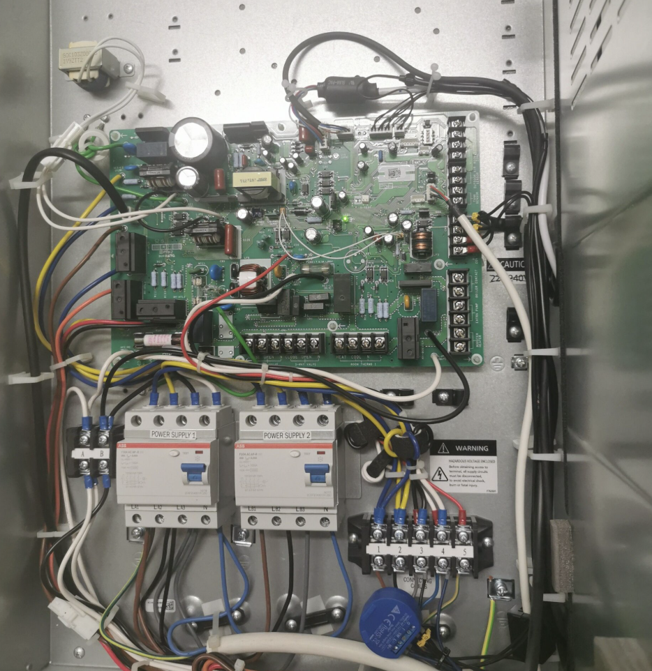
If the inverter’s mainboard has a DRM port, connect the MODBUS R2 module A and B to the inverter’s BMS port on pins 1 (B+) and 2 (A-).
If the BMS port is occupied by the battery communication cable, use the Y-splitter included in the inverter installation kit to make the connection, following the wiring diagram below.

Attention!
If the inverter does not have a DRM port, connect the MODBUS R2 module’s A and B to the inverter’s Modbus connector at pins 7 (A-) and 8 (B+).
If the inverter does not have a DRM port, connect the MODBUS R2 module’s A and B to the inverter’s Modbus connector at pins 7 (A-) and 8 (B+).
Module startup
⦿ Switch on the circuit breaker of the MODBUS R1 / R2 module or insert the fuse.
⦿ Check whether the white LED indicator on the MODBUS R1 / R2 module starts blinking rapidly.
⦿ Configure the MODBUS R1 / R2 module, following the instructions, to connect it to a local WiFi network with the strongest available signal. If necessary, add a WiFi range extender.
⦿ Check whether the white LED indicator on the MODBUS R1 / R2 module starts blinking rapidly.
⦿ Configure the MODBUS R1 / R2 module, following the instructions, to connect it to a local WiFi network with the strongest available signal. If necessary, add a WiFi range extender.
Fronius
Inverter configuration
In the Fronius web interface, the following settings must be configured in the Modbus Data Export view:
⦿ Modbus RTU Interface 1 must be set to slave.
⦿ Baud Rate must be set to 9600.
⦿ Parity must be set to none.
⦿ SunSpec Model Type must be set to int + PF.
⦿ Inverter Address must be set to 3.
⦿ Inverter Control via Modbus must be set to “On”.
⦿ Modbus RTU Interface 1 must be set to slave.
⦿ Baud Rate must be set to 9600.
⦿ Parity must be set to none.
⦿ SunSpec Model Type must be set to int + PF.
⦿ Inverter Address must be set to 3.
⦿ Inverter Control via Modbus must be set to “On”.
Module installation
Paigalda MODBUS R1 / R2 moodul vastavalt paigaldusjuhendile.
Tee sidekaabli (CAT5 või CAT6) abil ühendus MODBUS R1 / R2 seadme RS485 pistikus oleva A, B ja inverteri MODBUS pordi vahel:
⦿ M1+ -> A
⦿ M1- -> B
Tee sidekaabli (CAT5 või CAT6) abil ühendus MODBUS R1 / R2 seadme RS485 pistikus oleva A, B ja inverteri MODBUS pordi vahel:
⦿ M1+ -> A
⦿ M1- -> B
Module startup
⦿ Switch on the circuit breaker of the MODBUS R1 / R2 module or insert the fuse.
⦿ Check whether the white LED indicator on the MODBUS R1 / R2 module starts blinking rapidly.
⦿ Configure the MODBUS R1 / R2 module, following the instructions, to connect it to a local WiFi network with the strongest available signal. If necessary, add a WiFi range extender.
⦿ Check whether the white LED indicator on the MODBUS R1 / R2 module starts blinking rapidly.
⦿ Configure the MODBUS R1 / R2 module, following the instructions, to connect it to a local WiFi network with the strongest available signal. If necessary, add a WiFi range extender.
Module configuration
Device information
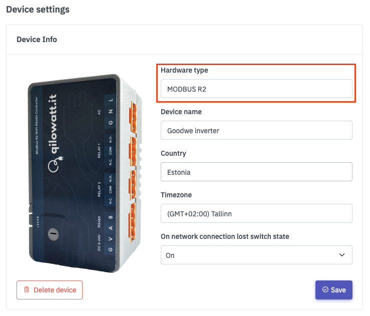
Vasakult menüüst liigu “Minu seadmed”, vali seade mille nimi on “Qilowatt-XXX”. Liigu alla poole ja otsi üles “Seadme info”, vajuta “Muuda” nupule.
Vali seadme riistvara tüübiks vastav moodul.
Sisesta seadme nimetus.
Vali seadme asukohariik (kasutatakse asukohariigi elektrihindasid).
Ning lõpuks salvesta.
Vali seadme riistvara tüübiks vastav moodul.
Sisesta seadme nimetus.
Vali seadme asukohariik (kasutatakse asukohariigi elektrihindasid).
Ning lõpuks salvesta.
Electrical device information
From the left-hand menu, go to “My Devices” and select the device whose electrical device information you want to change.
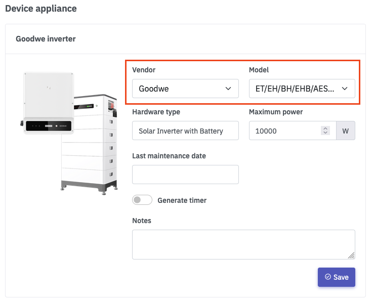
Scroll down and find “My Electrical Device,” then click the “Edit” button.
Select the appropriate manufacturer, model, and type of the electrical device.
To generate automatic sample timers, click “Generate timers” and then “Save.”
Scroll down and find “My Electrical Device,” then click the “Edit” button.
Select the appropriate manufacturer, model, and type of the electrical device.
To generate automatic sample timers, click “Generate timers” and then “Save.”
Solar inverter configuration
Inverter information
From the left-hand menu, go to “Inverters” and click on the appropriate inverter.
After the inverter page opens, click the “Solar Plant” button.
After the inverter page opens, click the “Solar Plant” button.
Solar plant
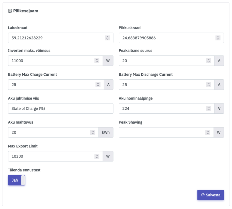
Fill in the fields according to the solar inverter information. When entering data, use a period instead of a comma.
Latitude / Longitude – The geographical location, required for solar production forecasting.
Inverter maximum power – The maximum operating power of the solar inverter.
Main fuse size – The size of the main fuse in the electrical connection panel.
Battery maximum charging current – The maximum current in amperes when charging the battery, for example: when purchasing electricity from the grid or from solar panels.
Battery maximum charging current – The maximum current in amperes when charging the battery, for example: when purchasing electricity from the grid or from solar panels.
Aku juhtimise viis – State of Charge (%) või Voltage. Akut saab juhtida nii mahtuvuse %-ga või pingega voltides.
Battery nominal voltage – The nominal voltage of the battery in volts.
Battery capacity – The capacity of the battery in kilowatt-hours (kWh).
Peak Shaving –
Maximum electricity export power – The maximum grid export allowance according to the agreement with the grid operator. For example, if no agreement exists, enter 0. If there is a nanogenerator agreement, enter 790 W.
Refine forecast – When enabled, the solar forecast for the upcoming hours is continuously updated.
Solar panel groups
Solar panel groups are required for solar production forecasting. A solar panel group is considered as one MPPT input in the inverter or as a set/array positioned with the same orientation and tilt angle.
Total power – The total power of the MPPT or solar panel group/array.
Tilt angle – The tilt angle of the solar panels relative to the ground, in degrees.
Azimuth – The directional orientation of the solar panels in degrees. See the “Suncalc” section.
Total power – The total power of the MPPT or solar panel group/array.
Tilt angle – The tilt angle of the solar panels relative to the ground, in degrees.
Azimuth – The directional orientation of the solar panels in degrees. See the “Suncalc” section.
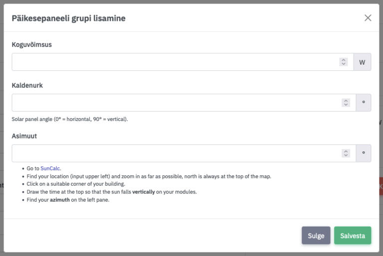
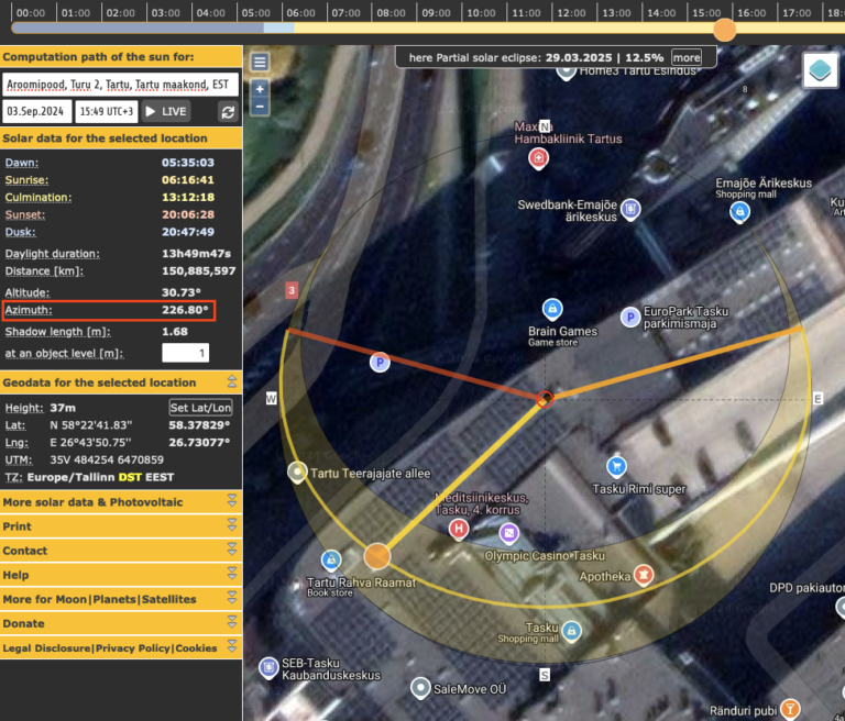
Suncalc
Open the website https://www.suncalc.org in your browser and enter the solar plant’s address into the search bar. Zoom in on the map and drag the central dot onto the location of your solar panels. Then move the sun position marker on the outer ring (or adjust the timeline at the top of the page) until the thick yellow line is vertically aligned with your solar panels.
On the left-hand side, a numeric “Azimuth” value in degrees will appear—this is the value you need to enter into the “Azimuth” field of the solar panel group.
On the left-hand side, a numeric “Azimuth” value in degrees will appear—this is the value you need to enter into the “Azimuth” field of the solar panel group.